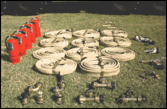
Figure 7-1. Major components.
| Critical Task: | 101-519-3317 |
OVERVIEW
Due to the extreme hazards associated with refueling aircraft in a theater of operations and the stringent quality requirements of aviation fuels it is imperative that all HTARS systems be properly maintained, assembled, and operated.
Lesson Description:
This lesson covers the procedures for directing the assembly, operation, PMCS, and disassembly of the HTARS system.
Terminal Learning Objective:
| Action: | The soldier will learn to select an HTARS site, supervise the assembly, operation, PMCS, and disassembly of the HTARS system, observe fire and safety precautions, and identify environmental considerations. |
| Condition: | Given subcourse QM5094. |
| Standards: | The soldier must score a minimum of 70 percent on the end of subcourse examination. |
The HTARS is a kit that consists of enough hoses, fittings, and nozzles to expand the HEMMT tankers capabilities to hot refuel up to four helicopters simultaneously using the on-board fuel-servicing pump. The equipment is lightweight, has manually operated controls, and is equipped with valve and swivel adapters that allow connections between camlock and unisex type fittings. This equipment can be used in forward areas. It can be transported in the storage box of the HEMTT tanker.
Discharge Hoses. The system consists of 2- and 3-inch discharge hoses. One 3-inch by 50-foot hose is used to connect the HTARS to the HEMTT tanker. Ten 2-inch by 50-foot discharge hoses transfer the fuel from the HEMTT tanker to the aircraft. Six hoses are used in the manifold and one in each of the four issue lines. There are 11 carrying straps for easy handling of rolled hoses.
Valves and Fittings. The following valves and fittings are components of the HTARS:
Nozzles. The HTARS is equipped with four types of nozzles. There are four CCR nozzles with unisex adapters. Four overwing nozzles can be mated to the CCR nozzles to perform open-port refueling. The system has one recirculation nozzle that can be connected to the HEMTT tanker to recirculate fuel in the system. It is equipped with a fuel sample port to obtain a sample of fuel. The recirculation nozzle mates to the CCR nozzle. There are four D-1 nozzles to equip the system for center-point refueling.
Overpack and Other Required Items. Each system has one overpack spare with additional parts and accessories. The following parts are in the overpack spares: one T-connector, one 2-inch by 50-foot discharge hose, one carrying strap for easier handling of the rolled hoses, 10 dust seals, two dust caps, and four grounding rods.
Other items of equipment are required to conduct aircraft refueling operations with the HTARS. A minimum of five fire extinguishers is required, one to be within reach of the on-board pump and one at each refueling point. Signs will need to be posted at the refueling site. Also, water cans and spill containers will need to be available.

Figure 7-1. Major components.
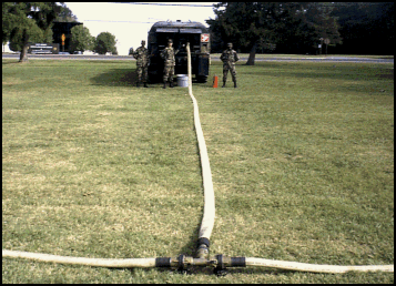
Lay out the HTARS (Figure 7-2) in a manner most practical for the situation. Avoid obstacles and take advantage of terrain features. When laying out the equipment, never remove a dust cap until you are ready to make a connection. This will prevent dust or particulate matter from entering the system and causing fuel contamination. Likewise, when disassembling cap equipment immediately after uncoupling. When laying out the HTARS follow the procedures below.
Position Vehicle. Select the most level ground to position the M978 HEMTT tanker. Avoid areas near bodies of water to avoid contamination and use the highest ground possible to prevent vapor accumulation. When positioning the vehicle remember the system should be laid out so that helicopters can land and refuel into a headwind or crosswind. Make the most use of natural concealment. Position the vehicle to allow easy exit without blocking any exits. After positioning vehicle, drive a ground rod at least 3 feet into the ground, attach the vehicle ground cable to the ground rod, and position fire extinguishers within easy reach, and post the "NO SMOKING" signs.
Connect System Components. Connect the 3-inch by 50-foot discharge hose to the suction hose on the HEMTT tanker (the tanker suction hose is connected to the bulk receptacle filtered on the HEMTT tanker). Connect the T-to the 30-inch discharge hose. Roll a 2-inch by 50-foot discharge hose from both sides of the T-and connect both discharge hoses to the T. Connect another T to the end of each 2-inch discharge hose. Roll out and connect two 2-inch by 50-foot discharge hoses to each outer tree. At the end of both outer 2-inch discharge hoses, connect an elbow fitting. Unroll and connect a 2-inch by 50-foot discharge hose to each of the two Ts and elbow fittings. Put FLOW handles in flow position after connections are made.
NOTE: The unisex fittings will not connect if the FLOW handles are in the flow position.
Connect Nozzles. Connect the type of nozzle to be used for the operation to the 2-inch discharge hose at each point. The CCR and D-1 nozzle connect to the 2-inch discharge hose. The overwing (open-port) and recirculation nozzle mate to the outlet of the CCR nozzle. Refer to TM 5-4930-235-13&P (Operators, Unit, and Intermediate Direct Support Maintenance Manual and repair Parts and Special Tools List for Closed Circuit Refueling Nozzle Assembly, Model Number 125-10,000 and Model Number 125-0505) for information on nozzles.
Ground Equipment. Drive a grounding rod into the ground 10 feet back from the end of each dispensing hose. Loop the dispensing hose at each point back to the ground rod and hang the nozzle on the ground rod hanger. Connect the clip of the nozzle grounding wire to the ground rod at each point. At each point, place a CO2 or dry chemical fire extinguisher. Also, place a spill container and a filled 5-gallon water can at each point.
Camouflage Equipment. Camouflage the truck and system to the extent required by the tactical situation. Natural concealment such as woodlines, hedgerows, vegetation, and natural terrain contours should be used when possible. Straight lines of the hoseline can be broken up by breaking branches and placing them under the hoseline to hold the branches in place

Figure 7-2. HTARS setup.
Preparation for Operation. Ensure all safety and environmental precautions have been taken. Verify that all safety and fire-fighting equipment is in place and serviceable. Check landing lights if they are required. Perform daily and before operations PMCS on the HEMTT tanker IAW TM 9-2320-279-10-1 (Operator's Manual, Volume No. 11 for M977 Series 8x8 Heavy Expanded, Mobility Tactical Trucks (HEMTT)) and on the HTARS TM 5-4930-237-10. Inspect the discharge hoses, valves and fittings, nozzles, and grounding systems. Ensure that all refueling personnel are wearing the proper protective clothing. As soon as the system is full of fuel and ready to operate each day, draw a sample from each nozzle. If the fuel does not pass tests and inspections. Do not use it. Isolate, resample, and send the fuel sample to the supporting laboratory, and await the laboratory’s instructions on disposition.
Sequence of Operations. The HTARS has two primary modes of operation, refuel and recirculation. In the refueling mode, fuel is pumped from the HEMTT tanker through the system hoses to the refueling points (nozzles). In the recirculation mode, the refueling nozzle (CCR or D-1) is disconnected from the refueling point and the recirculation nozzle is connected. The recirculation nozzle is connected to the HEMTT tanker and fuel circulates through the system hoses and back to the tanker. The HTARS can operate in both modes at the same time.
Refueling mode. To operate the HTARS in the refueling mode, follow these procedures:
NOTE: Ground the aircraft. Grounding of aircraft during refueling is no longer required by NFPA standards 77 and 407. Grounding will not prevent sparking at the fuel surface.
- Center point refueling nozzle operation. Remove the dust cover from the end of the nozzle body. Grasp the handles and hold the nozzle in alignment with the aircraft refueling adapter. Press the nozzle body against the adapter and turn handles to the right until the end of the nozzle mates and locks to the aircraft refueling adapter. Rotate the control handle to the full OPEN position. The pilot will signal when the tank is full. To disconnect, rotate the control lever to the fill CLOSED position. Grasp the handles and rotate the nozzle body to the left until it disconnects from the aircraft adapter.
- CCR nozzle. Mate the CCR nozzle to the fill port. Pull back on the control handle latch, and then push the control handle up toward the aircraft into the FLOW position. If the aircraft is to be filled completely, watch the back of the nozzle. A red indicator will pop out of the back of the nozzle when the aircraft tank is full. Pull back on the flow control handle to move it into the NO FLOW position. Unlatch the nozzle.
- Overwing (open-port) nozzle. Rapid refueling (hot) using the open-port nozzle is restricted to combat or vital training (Chapter 14, FM 10-67-1). The decision to use the open-port nozzle must be made by the commander. The open-port nozzle is mated to the CCR nozzle. The end of the nozzle is placed in the aircraft fuel tank adapter. Set the CCR nozzle to FLOW. Squeeze the control handle to dispense fuel. Watch the fill port when filling the tank. As the tank nears full, ease up on the trigger and finish filling more slowly. When the tank is full, release the trigger. Move the flow control handle on the CCR nozzle to the NO FLOW position. Be sure that flow has stopped completely before removing the nozzle from the fill port.
Recirculation mode. One recirculation nozzle is supplied with the HTARS. To recirculate the entire system, the recirculation procedure must be performed for each refueling point. To perform recirculation, follow the procedures listed below: